Wall plotter update #8: pulley hack, first prints and acquiring better parts for new plotter
After my previous post, a couple of relevant Instructables popped up offering more alternatives for various aspects of this project, some of which work quite well! After a few setbacks, I was able to fabricate a set of wooden pulleys, but they failed very soon after installation, leaving me to wonder what the next steps would be. I was almost certain I would have to 3D-print some custom parts, but this may no longer be the case!
Why the wooden pulleys failed
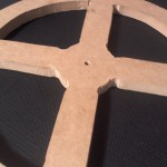 First of all, if you haven’t been following this project over the last few months (don’t worry, I don’t expect you to!) let me explain the issue about the pulleys I created. Originally, I had heard of people using small pulleys for their wall plotters and having negative effects – in particular, the string or wire for the pen carriage was overlapping itself as the pulley was wound and unwound, creating small, unpredictable variations in the pulley diameter, resulting in unwanted distortions over time. I thought I’d be smart by working out the math to find the ‘optimal’ pulley diameter which reduces overlapping without being too huge, which to me seemed to be about 10″.
After hitting a few snags in the fabrication phase, I finally ended up with two 10″ pulleys made from MDF and slapped them onto the stepper motor shafts. Unfortunately, the downside of having larger pulleys is a dramatic increase in torque, meaning even though the weight of the pen carriage was quite small, it was exerting a large force at the edge of the pulley. I don’t suspect that the motors would actually have a major problem with this extra torque requirement, but the press-fit joint between the pulleys and the motor shafts was not up to snuff. Since I didn’t know if this would work, I chose not to permanently epoxy the pulleys to the shafts, which mean that a lot of that torque was actually being applied to the area where the pulley touches the shaft. Pretty soon, the wood gave way and the holes in the middle of the pulleys widened up, and they no longer fit onto the motors.
Using sewing machine bobbins as pulleys
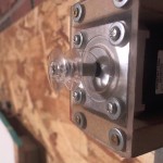 One of the Instructables that I came across recently used sewing machine bobbins as their pulleys, and seemed to have good results. I immediately went out to my local hobby store and picked up a pack for just a couple bucks. The inner diameter of the bobbins I found is about 7mm, whereas the shafts of the stepper motors I have is about 5mm. A couple layers of electrical tape makes up the difference, and also provides a bit more friction to hold the bobbins in place. Using sewing machine bobbins as pulleys has a couple of advantages it seems:
- Small outer diameter, so the resulting torque from the load of the pen carriage is kept to a minimum.
- Two flanges keep the string / wire on the pulley pretty well.
First prints!
I updated my code to reflect the new dimensions of my pulleys and set up a serial connection to my Arduino board using the Arduino IDE’s Serial Monitor tool. From here, I could send my machine individual commands and evaluate how well they get executed.
In the first print, I brought the pen up to the top left corner, then made it follow a snaking path downward in order to see whether the ‘straightness’ of the various lines change as a function of Y axis distance. Every line in this drawing was meant to be completely straight, but instead each line is curved. As you can see, each line is curved pretty consistently, which tells me that the bot thinks that it is either higher or lower than it really is. Notice that all of the vertical lines are very straight, albeit slanted. This tells me that there is some vertical distortion, but little horizontal distortion. Furthermore, the lines are quite faint, which tells me that there is not a lot of friction between the pen and the surface.
[flickr-gallery mode=”photoset” photoset=”72157629914715221″]
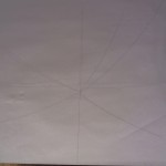 Next, I manually re-measured the coordinates of the center of the canvas and I found that the Y value I had calculated was larger than it should be. This means that the bot thought that it was starting its movement from slightly lower than it really was, creating a vertical distortion on the paper. I also noticed that the pulley dimensions I had entered weren’t quite right, so I updated those and uploaded the code. For this print, I made the bot move along only one axis at a time, returning to center after each time. Then I made the bot move diagonally in the four quadrants to see how well those lines are carried out.
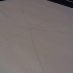 All of the lines seemed to come out much straighter this time, but not perfect yet. A small amount of jitter is expected (even desired!), but the bot should be able to trace the same lines over and over with very little deviation. I think this is due to the design of my pen carriage, as well as some interference from the knots on the pulleys.
Plotter #2 underway
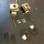 Since I now have some extra cash to burn (thank you student loans), I thought it’d be a good idea to build another wall plotter of comparable size using different parts. I made a few cost-cutting substitutions in the first plotter, and I’m really curious about how much they affect the overall print quality. Therefore, I’ve acquired parts that more closely match the original parts list for the Der Kritzler (including some pulleys sent from the original maker of Der Kritzler, Alexendar Weber!). Found a much cheaper source for stepper motors, and picked up some cool timing belts for super-cheap. With these new parts, the wire will not spool up on the pulley at all, and I can be much more confident that nothing is being stretched or warped from tension.
Making a new plotter will also give me the opportunity to do a little better with the actual construction of the canvas, to try and hide the inner workings a little bit from the users (something I don’t normally like to do, but in this case is probably smart).
Next steps
This week I will be continuing to calibrate my first wall plotter (using the sewing machine bobbins) to get more accurate prints. If I can solve the problems with the curving and distortion, I’ll start on the conceptual art aspects of the project and create a few arstsy prints, which I have had already made a good deal of progress on. I’ll also be working on constructing the new wall plotter, obviously, and getting it looking all professional and nice. I also need to design a better, more reliable pen carriage for both machines, which I’m hoping won’t be too challenging. More to come!