Wall plotter update #5: pulley and wall mount fabrication, ready for installation
In the last couple weeks I have been working on actually fabricating the pulleys and motor mounts to move my wall plotter project forward, but have been hitting more than a few roadblocks in doing so. After looking into several departments on campus, I have realized that very few people actually make anything anymore, and that some departments have equipment, but refuse to let students use it! This forced me to look into machine shops around town, which can get quite costly for hobbyists. Luckily, after doing a few things the ‘hard way’, I was put in touch with the Sculpture department on campus, which has given me access to their wood shop to work on these projects!
Fabricating the wall mounts
Firstly, I needed to create a way to mount my stepper motors to a wall using available resources. If I had a Makerbot Replicator or Thing-o-matic, I could easily design a solid plastic NEMA 17 motor mount and print it out in half a day, but since I don’t have one, I had to make it myself.
I began by cutting down some extra MDF stock I had leftover from the pulleys. I then attached one small angle bracket to each piece using 6×32 machine screws, nuts and washers, leaving about a half inch of space for the faceplate screws to go into. Next, I cut out two small pieces of plexiglass to serve as faceplates to mount directly to the stepper motors. This was a bit more difficult and messy than I expected, but I got it done just the same! Next, the faceplates were attached to the ‘ledges’ of MDF, and the stepper motors connected using M3 screws. The angle brackets should make it relatively easy to attach the whole assembly to a wall.
[flickr-gallery mode=”photoset” photoset=”72157629213706894″]
Fabricating the pulleys
Cutting the circles
While working on the motor mounts, I also worked on fabricating the pulleys. In my previous post, I identified that the ideal pulley size for my wall plotter is about 10″ in diameter. So, I went out and got myself a compass and some MDF, and marked out two 10″ circles, then cut the stock down a bit using my table saw. Next, I secured the square pieces into my bench vise (another recent purchase) and careful used a coping saw to follow the marks from my compass. In case you’re wondering, yes this did take a long time and yes my arms were pretty sore the next day! I don’t have much in the way of router accessories or skills yet, so that option didn’t pan out for me (in fact, check out this photo to see the result of my attempt to make a circle cutting jig).
Press-fit holes for non-permanent shaft coupling
To attach the pulleys to the motors in a non-permanent way, I drilled a hole in the center of each pulley slightly smaller than the shaft of the motor shafts so they can be press fit together. Luckily, by this point I was allowed access to my campus’s Sculpture lab, complete with a basic wood shop, so it was quite easy.
Cutting away stock to reduce weight
As you can see in the later photos below, I decided to cut away stock in each pulley to reduce weight. After cutting stock from one pulley, I did a quick ‘feel’ test and saw that the cut-up pulley felt about half as heavy as the other full circle. This should help those motors out a little bit!
Adding a groove to the edge
Finally, I used a rotary tool to add a small groove around the edge of the pulley to help guide the fishing line during winding and unwinding. I plan to add either some flanges to the pulleys or some sort of guide bar to help feed the line even more, if necessary.
[flickr-gallery mode=”photoset” photoset=”72157629579371295″]
Next steps
At this point, I feel that the bulk of the planning and fabrication phases are done, and I’m ready to go ahead with installing everything in the space and begin testing out applications. Hopefully I can get the motors and pulleys mounted on the wall this week, and at least begin wiring everything up (once I get a hold of a computer and secure space).
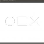
 Besides the mechanical aspect of the plotter, there is also a collection of software needed to get everything running. I have already spent a good deal of time working on it and feel confident that there won’t be any major problems. The thumbnail you see to the left is a screenshot of the control software running, which translates SVG files into a set of instructions for an Arduino to carry out, which are sent via a serial connection to the hardware system in real-time. So far, everything is working perfectly!