Wall plotter update #6: testing platform built, few small hurdles yet to overcome
 In my previous progress update, I described the pulleys and wall mounts I created to get my wall plotter up and running. Even earlier, I successfully tested the electronics and got them working. At this point, I felt the complete system was ready for testing, so I began looking for a place to install it all.
So far, no ‘perfect’ installation site has been found, so I decided not to waste any time waiting to find one and just install everything on a temporary test platform in my apartment. Ideally, I wanted to use this machine on a wall to make large plots, but for now, I will be concentrating on making it work at a smaller scale. While I’m working on this, I’m also trying to hack together a simple, lightweight pen carriage.
Iteratively designing a modular pen carriage
Other wall plotters use other kinds of pen carriages to hold a drawing implement perpendicular to the drawing surface, often utilizing 3D printed parts or found materials. Since I do not (yet) have access to a 3D printer, I opted for the latter approach. I had some plexiglass leftover, and thought I could cut it into a simple triangular structure to make a minimalist (and cool looking) carriage. I started out simply using two pieces, fastened together using a bunch of screws, nuts and washers, but soon realized that this wasn’t very modular. This made it hard to mount the servo to the correct height, and adjust that height depending on the drawing implement.
As of today, the current design of my pen carriage can be seen in the following Flickr photoset. It is made of three layers of plexiglass held together using three machine screws (one per corner) and nuts. The actual piece that holds the drawing implement is simply a small section of PVC tubing with a M3-tapped hole. This is then epoxied onto a small piece of plexi which can be non-permanently fastened to the top-most layer, so that if the threading wears out, it can be replaced easily.
[flickr-gallery mode=”photoset” photoset=”72157629363416820″]
Installing everything onto a test platform
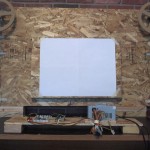
Rather than diving right into installing everything at a public venue, I decided it would be best to instead install everything on a piece of plywood and try to get it working in my apartment. Besides, we still don’t even have a good place to install it in public anyway! So, I took a spare piece of plywood (roughly 30×48″) that I had laying around my workshop and attached the motors to the corners. Next, I used the formulas I developed to approximate a reasonable canvas size and punched the numbers into my software.
After installing the motors onto the plywood, I attached the pulleys to their shafts. Next, I suspended the pen carriage from the pulleys using fishing line. Finally, I wired up the motors to the electronics systems and uploaded the appropriate software.
Today I actually had a test run, where I applied power and loaded a simple SVG file into my software. Unfortunately, things got a little crazy. Rather than single commands being sent from my PC to the Arduino board on by one, thousands of messages were sent with very little delay! All that happened was that the pen carriage slowly moved to the lower right, for reasons I don’t quite understand yet. Furthermore, it looked like the pulleys were not spinning correctly, as though the weight of the pen carriage was ‘pulling’ them in one direction. This week I will be troubleshooting these problems, which I will try to document here. The trick, for me, will be staying positive throughout this process and remembering that “any progress is good progress”. Some even say that “there is no such thing as failure”, but I will withhold judgement on that until later ;)
[flickr-gallery mode=”photoset” photoset=”72157629339339722″]
Next steps
Like I said, I have already run into a couple of snags with my test platform, so I will be spending the next week or so working on resolving the issues and getting the plotter up and running. While working on the mechanical and physical aspects of the project, I am also working on creating some interesting plots for the eventual installation. Right now, I have about a half dozen different ideas for ways to use the plotter, and am hoping to make it open and accessible for students. Ultimately, after making a few plots that I choose, I plan to somehow incorporate some degree of interactivity for the plotter, allowing students and passerby’s to control the plots in some way. Examples include printing tweets, plotting ambient noise levels over 24 hours and creating a ‘puppy dog’ pen carriage that follows passerby’s and jitters in excitement.
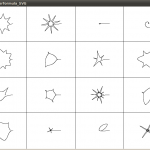
 After I get the initial system up and running, I will run a series of simple plots to calibrate the system and test its speed and accuracy. Once things are looking good, I’ll use the system to plot a generative piece I am working on in Processing that creates random variations of the superformula and arranges them into a grid. The sketch is producing the expected results right now, but I still need to implement all of the graphics using the Geomerative library, so that I can export the results in an SVG file, which can be drawing by the plotter. More to come!