Wall plotter update #3: electronics assembled and tested on breadboard
Last week, the electronics for my wall plotter were acquired, and are ready to be assembled and tested. This week’s activities were obvious: go for it. This was simple enough that I actually spent a few hours writing up a length, in-depth article about how to assemble and test all the electronics, but then I realized that that is not the point of these updates. These updates are meant to be quick documentation of on-going progress, not in-depth technical articles explaining every piece of the process. Once the plotter is up and running, I will publish a huge ‘how-to’ article that looks at every piece of the system up close, so just hang on!
Prep work
Before doing anything else, I needed to do two things: prepare the ATX power supply and assemble the A4988 stepper motor drivers. Assembling the drivers is simple; they ship with 0.1″ male headers, and all I needed to do was solder them onto the boards.
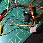
The ATX power supply is also simple to set up; just put a small wire, like a piece of anchor wire, between pins 15 and 16 of the motherboard jumper to enable the power supply without needing to be plugged into a motherboard. Next, I cut off a 4-pin molex connector and tapped into the ground, +5V and +12V lines. The +12V line provides the raw power for the stepper motors, and the +5V line powers an Arduino and the logic side of the stepper drivers.
Breadboarding the entire system
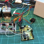
 Next, I set up the motor drivers, stepper motors, servo and Arduino on a breadboard following tips and documentation from the original Der Kritzler article, the various Polulu product pages and component datasheets. Much, much more can be said about how this is done, but like I said in the introduction, this is just an update, not an in-depth technical article.
Testing the system with a simple Arduino sketch
With everything connected and triple-checked, I wrote a simple Arduino sketch to test out each component, one at a time. After a little bit of adjustment to the current-limiting trimpots of the motor drivers, everything was working quite well:
Next steps
For the next week, perhaps even few weeks, I will move away from the electronics and code aspects of this project and take a very close look at the mechanical engineering aspects of it. In particular, I need to design a way to hold a pen perpendicular to the surface of the final canvas, and move it how I want using custom-made pulleys. Some very fun (seriously!) and practical calculations will be in order to figure out important factors like pulley size, stepper motor speed, line tension / weight, center of gravity for the pen carriage and so on. Call me weird, but this kind of excites me!
After the mechanical planning is finished, I can begin actually designing pieces to be machined, and get around to installing the plotter at it’s target destination. This will also include setting up the Der Kritzler software environment to get the hardware and software working together. I would estimate that we are about one month away from the installation / testing phases, so stay tuned!

