Wall plotter update #2: electronics acquired, installation space decided and ‘how-to’ in the works
This week, I received the electronics parts for the wall plotter from Pololu and began writing a complete ‘how-to’ article to help others create their own wall plotter using the approach I’m following.
From left to right, the parts are:
- 1x – micro servo
- 2x – A4988 stepper motor drivers
- 2x – stepper motors
In my previous update, I mentioned that I had decided to focus on replicating the Der Kritzler project, which is how I decided on the parts above. However, since not all of the parts used in the original Der Kritzler project are sourced in the US, I had to make some substitutions, which need to be noted.
Important note #1: different stepper motors
The two parts that couldn’t be perfectly sourced in the US were the stepper motors and the power supply, though I have found suitable substitutes. For the stepper motors, I found a couple that should work perfect at Pololu. Here’s how they compare to the original motors used by Der Kritzler:
| Pololu motor | Reichelt motor | |
| Type | Hybrid | Bipolar |
| Steps per rev | 200 | 200 |
| Voltage | 4V | 5.3V |
| Phase current | 1.2A | 1A |
| Form factor | NEMA 17 | NEMA 17 |
| Price | $17.95 | ~$31.09 |
| Source URL | Product page | Product page |
| Datasheet | Datasheet | Datasheet |
The most important difference between the motors is the fact that mine are hybrid motors, which means it can be connected either as a unipolar or a bipolar stepper motor. In this project, I will want to pay close attention to the colors of the wires, as they may not be the same as a bipolar motor.
Important note #2: different power supply
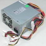
 The original Der Kritzler used an adjustable power supply that may or not be capable of driving the motors at their maximum possible current. To save myself some money, I decided to use a helpful trick I learned about a year ago to use a standard ATX power supply as a general-purpose power supply. The key advantage of these power supplies is that you can get them extremely cheaply and they will deliver a large amount of current for your projects. In fact, you can probably pick up a used or overstocked one for next to nothing at your local PC repair store.
Installation space
Last week I took measurements of the space that this plotter will be installed in, a section of bare wall in my university’s Fine Arts Building. I knew from the beginning that my plotter’s dimensions weren’t going to be the same as Der Kritzler’s, so I have been checking out the source code to figure out which variables are relevant to the canvas size, and how I can increase or decrease the size of the canvas however I want.
More details will be posted in the future about how I calculated the approximate canvas size based on these measurements, but for now I’ll just mention that I expect the canvas size to be about 7×6′ in size.
Complete ‘how-to’ coming soon!
Once the plotter is tested and installed, I’ll publish a big, complete article compiling all of the information from these mini updates so that others have one single reference they can use to create a wall plotter from start to finish. I’m already mostly done with it, just need to get miscellaneous photos and flesh out the last phases as they happen.
Next steps
Over the coming week, I will be assembling my electronics on breadboard and testing everything out to make sure it works, and that I understand how it works. If everything checks out, I’ll be setting up the full Der Kritzler firmware and software and trying to send commands using the same system that’ll be in place in the final installation. I’ll also be thinking about the design of the pulleys and how to suspend a pen over the surface using wires and a carriage, though I am not going to make that a priority until the electronics testing is complete.
