Wall plotter update #1: new name, code and parts
Renaming the project to “wall plotter”
When I first started looking at creating a wall plotter drawing machine, I was strongly influenced by an Instructable’s article from Sandy Noble called Polargraph Drawing Machine wherein he outlines a selection of similar projects and discusses his contributions to the idea. By starting with this project as a resource, I gained the impression that this particular kind of drawing machine was called a “polargraph”, when in fact, its more accurate to say that this is a wall-mounted plotter or, even more generally, a drawing machine. However, since I will no longer be trying to replicate this particular implementation, I can’t say that I’m working on a polargraph any longer. From this post on, we’ll be referring to this project as a wall plotter or drawing machine, and maybe a snazzy name will be generated later.
Shifting focus to the Der Kritzler
At first glance, the Polargraph project seemed like the best documented, and the best place to start for someone who wanted to make their own. However, once I dove into the code and planning a bit further, I met with more and more difficulty. At first, I decided that the best way to understand how the Polargraph worked was to pick apart the code, but upon doing so, I realized that the code was poorly documented, erratic and bloated – so much so that the developer had completely run out of space on the Arduino and was having to employ all sorts of hacks to fix more and more things into the sketch. There is a large amount of unnecessary code, inconsistent syntax, and a frustrating lack of separation between structures. I do not mean to bash on the Polargraph developer too much, as his intentions are good and his personal results speak for themself, but as far as using the Polargraph project as a platform to implement my own drawing machine, it became very unappealing, very quickly.
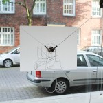
 Around the same time as the Polargraph project, Tinkerlog created a very similar, but much better executed project that they called Der Kritzler. Perhaps my enthusiasm about the Polargraph project blinded me to the possibility that Der Kritzler would also have source code available, but whatever the reason, I ended up thinking that Der Kritzler was a one-off project that was created mostly as a PR stunt for some artsy company (forgive me, Tinkerlog :)). I was very pleasantly surprised to realize that Tinkerlog actually released all of the source code for their project, which also used a Processing sketch and an Arduino sketch.
The main difference between Der Kritzler and the Polargraph project is that Der Kritzler was created by a seasoned, professional programmer who knew how to write beautiful code. While Der Kritzler only provides a small amount of explicit documentation, it is clear, concise and functional. Furthermore, the code is so well-organized and executed that it requires no additional documentation (if you’re a good enough programmer to read it). Beginners, take note: good code can act as its own documentation! Go ahead and follow the link below to browse the code repo on Github:
Updated parts list
Since Der Kritzler utilizes a slightly different way of controlling stepper motors, I decided to update my parts list to match theirs, just so I didn’t have to worry about porting the code to work with a different type of motor driver.
- 2x stepper motors from Polulu
- 2x A4988 stepper motor drivers from Polulu
- 1x micro servo from Polulu
- 1x Arduino Duemilanove or newer clone (Freeduino)
Next steps
Over the coming weeks, several issues need to be addressed, and components fabricated or sourced. Luckily, I have time on my side and can afford to take things at a comfortable pace, and take the time to thoroughly understand each component of this system as it is built. Hopefully, this will constructively add helpful information to the drawing machine community and make this particular kind of drawing machine just a little bit more accessible to others.
- Take measurements of installation space to see how big of a drawing we can make.
- Determine how to attach the stepper motors to the wall.
- Figure out a way to accurately move the drawing implement around. Der Kritzler seems to simply use fishing line, though the Polargraph project uses beaded cord and 3D-printed sprockets.
- Generate graphics to print on the wall. I’m thinking of using Processing to generate interesting paths using an L-system or Brownian motion.
