Prototype electronics (rev A) for Eyewriter 2.1 built and tested
For the past few months I have been working on fabricating, assembling, testing and debugging the prototype electronics system for the Eyewriter 2.1 open-source eye-tracking system. Quite a lot of work has gone into this particular update, as I didn’t want to post small bits of progress here on my blog (I use Twitter, G+, Facebook and Flickr for that). Instead, I wanted to make sure that I hit a good personal milestone before I officially wrote about it. So here’s the milestone for this update: the electronics have been tested and are working!
Fabricating the circuit boards
The very first thing that needed to be done was to actually have the circuit boards fabricated. In my previous update, I shared the first revision of board designs and discussed how it all works. The most recent updates are always available through the official Github repo.
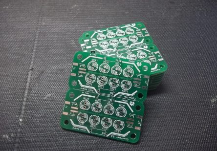
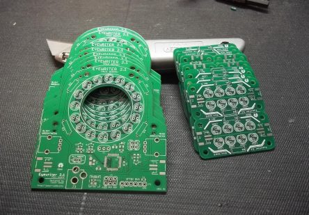
I used Seeed Studio’s Fusion PCB Service to fabricate these boards, which I’ve always had good success with in the past. I panelized the glint modules (two per panel) so that each order would yield twice as many boards (the panelized PCB is also available on the Github repo). I ordered 10 of each of the boards – the main board and the glint modules, with a total cost of $46.60. Here’s how that breaks down:
- 10 x main board modules = $24.90
- 10 x glint modules = $9.90
- Shipping = $11.80
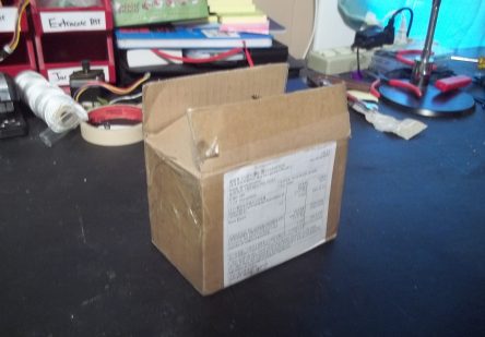
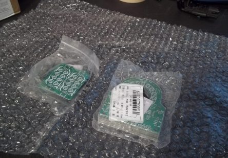
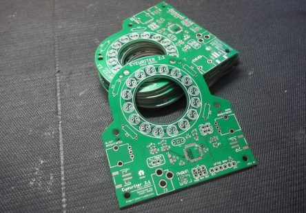
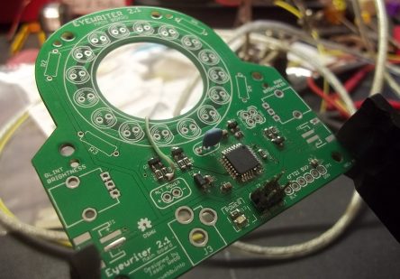
About two weeks later, I received these beautiful PCBs in the mail:
Soldering components and programming issues
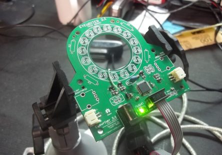
While the boards were being shipped I ordered a set of electronics from DigiKey to solder to the board (the BOMs are available on the project wiki and the official Github repo). As soon as the PCBs arrived, I soldered an ATMega328 to one of the main boards and all of the supporting components, then connected my USBtinyISP to the on-board ICSP interface and attempted to flash the Arduino Uno bootloader through the Arduino IDE. No dice.
It took me a week or two to figure out what was going on, and boy was that a frustrating time. The programming circuit was so simple that I thought I was losing my mind trying to troubleshoot it – there are only 3 parts on the board, what could possibly be going wrong?!
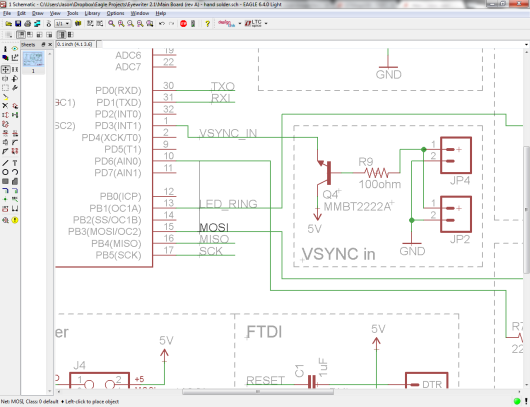
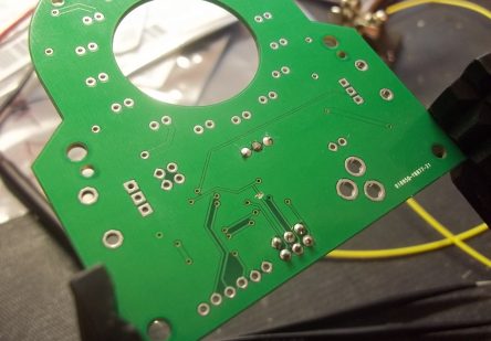
A couple of users on the Arduino forums convinced me that there must be a problem with the ICSP routing – maybe I had the header on backwards, or mirrored, or on the wrong side of the board. While I was working through the logic of this possible issue, I realized that one of the traces on the PCB design going to the ICSP was combined with another trace that it definitely should not be. I triple-checked the net labels in the Eagle schematic and found a really, really funny issue: I labelled the wrong route, then moved the label to the right route!. This means that when you look at the schematic, it looks completely correct, but the PCB design doesn’t lie.
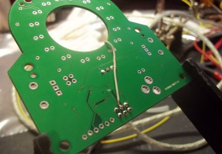
I cut the traces that should not be connected, then used a piece of jumper wire to connect MOSI to the correct pin of the ATmega328. I tried flashing the bootloader again using the ICSP interface and it worked perfectly!
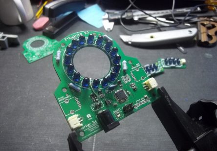
I then went ahead and soldered the rest of the components to both the main board and two glint modules and immediately uploaded a sketch via the FTDI interface (after soldering a 1uF capacitor to the reset line) that just flashed the central ring of LEDs once per second. As you can see, it worked!
Creating interconnects for the glint modules
 Making 2-pin JST cables
To connect the two glint modules to the main board I opted to use 2-pin polarized JST interconnects, which turned out to be pretty annoying. I tried to assemble the cables myself, and no matter how careful I was with the crimper or whatever kind of wire I used (stranded or solid), the crimp contacts would snap off after some pretty minimal stress testing.
Eventually I just gave up trying to make my own interconnects and ordered some from Adafruit. I couldn’t find any sources for cables that had a 2-pin male JST connector at both ends, so I actually had to order pairs of these cables and solder them together to create a complete cables for the Eyewriter. This works fine for prototypes, but would not work during a production run, so I still need a better solution than JST.
 Thinking about other kinds of interconnects
I realized that if I was having significant problems with the durability of JST connectors, so will any potential users / customers in the future. I looked for alternative interconnects that would be rugged and easy to assemble or acquire and just kept turning up empty. There are options, but none of them are any better than JST.
Then I realized that I don’t necessarily need to use interconnects that are specifically meant for connecting two circuit boards together; I could use something like 2.5mm microphone jacks and cables! These are very rugged, easy to use (for the designer and the user) and easy to source.
Testing the LEDs on the glint modules and main board
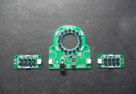
After putting together a couple of 2-pin JST cables I was finally able to connect my glint modules to the main board and write some simple code to flash the LEDs and test them out. I created the following simple Arduino sketch and uploaded it to the main board (followed by a video of the resulting behavior):
Next steps
With the glint modules and main board LEDs working, I now need to synchronize the flashing of the various LEDs to an external camera. The goal will be to tap into the vertical sync (vsync) signal of a modified PS3Eye camera and alternatively flash the glint module LEDs and main board LEDs in sync with the framerate of the camera. However, actually tapping into this vsync signal is ridiculously difficult, and I have yet to do it correctly without ruining a camera!
Once the LEDs are flashing with the framerate of the camera I can begin assessing the desktop software included with the original Eyewriter project. I tried to fix the original code but without having strong C++/openFrameworks skills this proved to be a bit much. After a couple months of fruitless struggle one of the original programming team members sent me a working copy of the software that he came across, which I was able to get to work. Once my camera and electronics are working I can begin the process of updating this software.
