ShapeOko CNC build log #2: assembling, wiring up and testing the electronics (it’s alive!)
Bit by bit over the last few months I’ve been making progress on my ShapeOko CNC mill. I have already assembled the mechanical system and attached the stepper motors and belts, but I hit a bit of a snag (or two) when it came to the electronics system.
Good news and bad news
Following a tip from the ShapeOko forums, I ordered some electronics components from a website called Reactive Substance on November 8th. A few weeks later, nothing showed up. I e-mailed the guy who was selling the kits and found out that my order was never sent. A few days later I received the shipment and immediately got to assembling. However, once I had it all assembled I realized I was missing the heatsinks for the stepper motor drivers, which should have been included in the shipment! Another round of e-mailing and waiting and I finally had everything I needed to wire up the ShapeOko. Only problem was that by this point, the Spring semester had started up and I didn’t have much time to spare on the project! Luckily, I now feel like I have a sense of control on my activity at this point in the semester so I’ve been able to get back on the horse and make small bits of progress on the project again.
About the electronics system
The ShapeOko CNC mill shares a lot of components with other popular digital fabrication tools out there like 3D printers and laser cutters. For example, all of these machines use stepper motors, belts and pulleys to move some kind of device around on three axes (X, Y and Z). For 3D printers, that device is an extruder, but for CNC milling we can use a rotary tool like a Dremel or a router (I’ll be using a modified DeWalt DW660 trim router).
Basically, the entire electronics system consists of three or four stepper motors, beefy motor drivers to control these motors and a microcontroller platform that can tell everything what to do. Some systems out there (especially in 3D printing) have all of these circuits on a single board (see Printrboard and RAMPS), but these are a bit more expensive than I wanted right now. Instead, I chose to go with a relatively simple system where three or four stepper motors are attached to a shield that can be stacked onto an Arduino. I already had a spare Arduino or two laying around, so it seemed like the cheapest and simplest option to start with.
Assembling the electronics
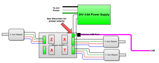
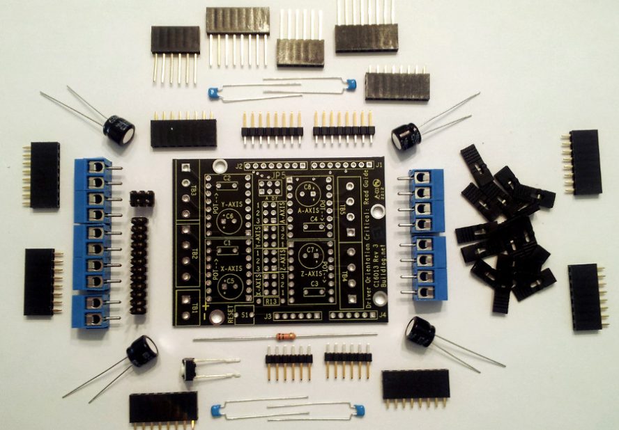
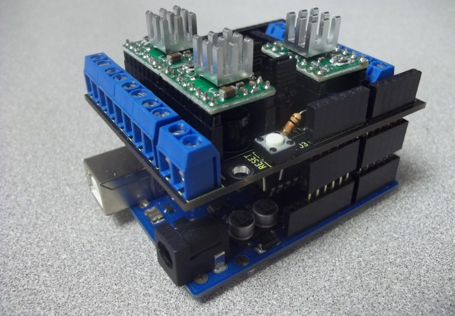
The electronics system I opted for is really a simple Arduino shield that gives access to up to four specialized stepper motor drivers. These drivers come preassembled and can literally just be dropped in place once the shield is assembled. The shield stacks conveniently onto a standard Arduino, reducing complexity quite a bit.
Assembly is easy, with my only gripe being in the assembly instructions. They only seem to exist in video form, which is great for absolute beginners, but somewhat annoying for experienced electronics nerds. Yes, I know what a soldering iron is, yes I know what capacitor looks like, now show me the important stuff!
Flashing GRBL onto the Arduino
 Creating software that controls multiple stepper motors with the speed, accuracy and efficiency required to successfully operate a machine like this is no small task. Some electronics solutions treat the Arduino has a simple translator, requiring an active connection to a full PC running complicated software to do all the dirty work of moving the various motors around.
The solution that I’m working with, GRBL, instead treats the Arduino as a more standalone platform, including all of the necessary complicated bits to carry out operations on the stepper motors. You just give it a long list of standard commands (called G-code), and it will know everything it needs to know about executing it.
Uploading GRBL to the Arduino is not quite as simple as uploading a normal Arduino program. You have to compile a .hex file from the GRBL source code, containing all of the variables that are specific to your machine (things like the pitch of the timing belts and the number of steps in a mm). Thankfully the ShapeOko wiki contains a pre-compiled .hex file with everything set up!
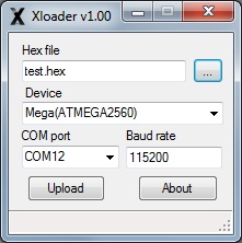
The .hex file is easily flashed onto the Arduino using a program called Xloader.
Wiring up the electronics
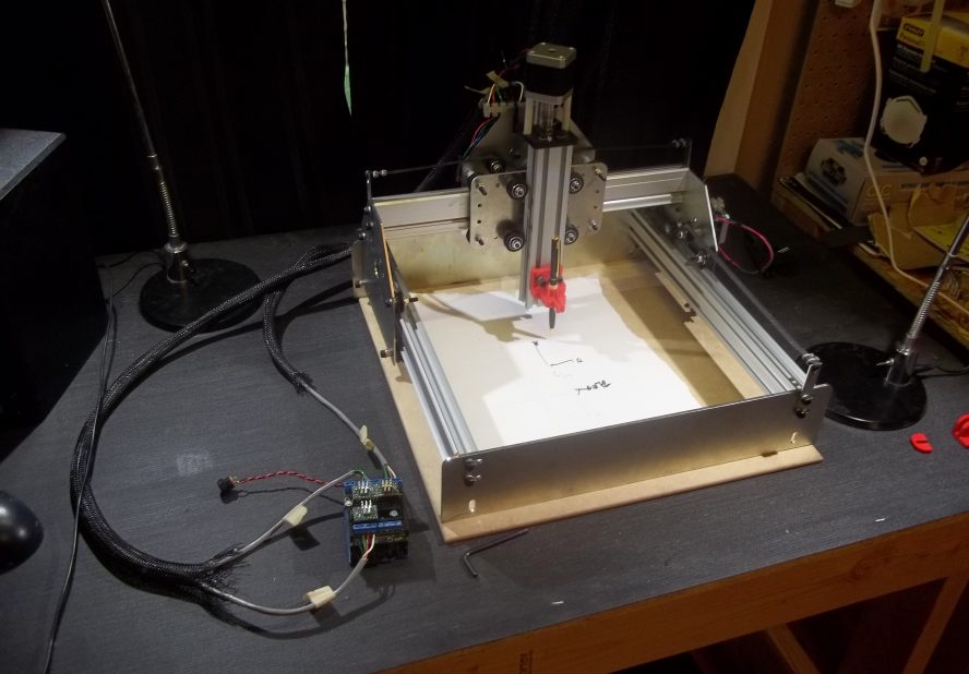
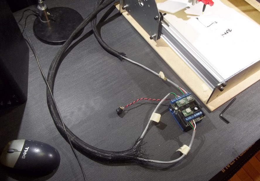
Connecting each of the three stepper motors to the electronics platform is a matter of cable management; you can be as tidy or as sloppy as you want. The tricky thing is that each motor is attached to a moving platform, so the cables need to have enough slack to allow it to move, but be kept out the way of all the moving bits.

Each stepper motor has four wires, which I chose to bundle together using zip ties. Each stepper motor is connected to the Arduino shield via four-conductor cables run through some neat snakeskin cable sleeves that I had laying around. When I was all finished, I was surprised at how flexible and clean the result was!
Testing it all out
 With the electronics all wired up and the Arduino flashed with GRBL, the only thing left to do would be to test it all out and see if anything catches fire! I really just wanted to test the three stepper motors out and make sure they do what I expect them to do before I slapped on a rotary tool and make things really dangerous.
First I used a nice little app called Grbl Controller (right) to send individual step commands to the different axes of the mill, just to see that all of the motors work OK in both directions. To me they appear to work, but I also am very new to the world of CNC, so who knows. I hope I set the step resolution of each axis correctly, because it seemed like it was only making very tiny movements – but that might be a good sign.
 Following the ShapeOko wiki, I loaded a “hello world” G-code file that draws the word “ShapeOko” in two-dimensions (see the video below). Using Grbl Controller it seemed like there was a slight pause after every command, so I instead sent the commands using another program called G-code Sender (left). The motion looked good to me, so I tried to tape a Sharpie onto the platform and have it draw it on a piece of paper. Unfortunately, the Sharpie just kept ripping away from the tape, so I’m going to 3D print a nice little bracket to firmly hold it in place soon.
