First Lumiboard prototypes and lessons learned
Lumiboard is a compact platform for controlling almost any kind of LED package from small discrete LEDs, to high-power RGB LEDs to digitally-addressable RGB strips. It includes a Bluetooth transceiver so you can control it through a smartphone or tablet, an external sensor board for reacting to audio, ambient light and temperature and much more! Originally designed specifically for making fun lamps, the project has been growing to become a programmable Arduino-compatible platform for controlling just about any type of LED you could want!
This post is about the very first steps I’ve taken in making the Lumiboard, but if long posts aren’t your thing, here are the essential links:
- View all posts on this blog related to the Lumiboard: https://jwwpheadless.com/tag/lumiboard
- Watch the project activity on my personal wiki: https://jwwpheadless.com/wiki/index.php?title=Lumiboard
- Watch for activity on my Flickr profile: http://www.flickr.com/photos/zenwebb/
And most importantly, you can grab all of the latest source files (Eagle files, BOMs, firmware) at the project repo on Github:

Project inception and motivation
For about two years now, I’ve wanted to create a controllable RGB LED lamp that I could sell to people mostly for fun. I started by hooking up some big fat ceramic power resistors to an RGB LED and driving it with a ULN2003 and an Arduino, and the basic approach hasn’t really changed since then. What has changed in the last couple years is my level of experience with Eagle and my ability to plan and execute personal projects – its really neat for me to see how much things have changed over time!
Last year, I thought it would be cool to make a small circuit board that had all the essential components for driving RGB LEDs, but also as many fun extras as possible, including sensors, a Bluetooth transceiver and lots of off-board connections for expansion. However, after spending a couple of months working on it, I came across an extremely similar project that made me question whether my little board would offer anything new.
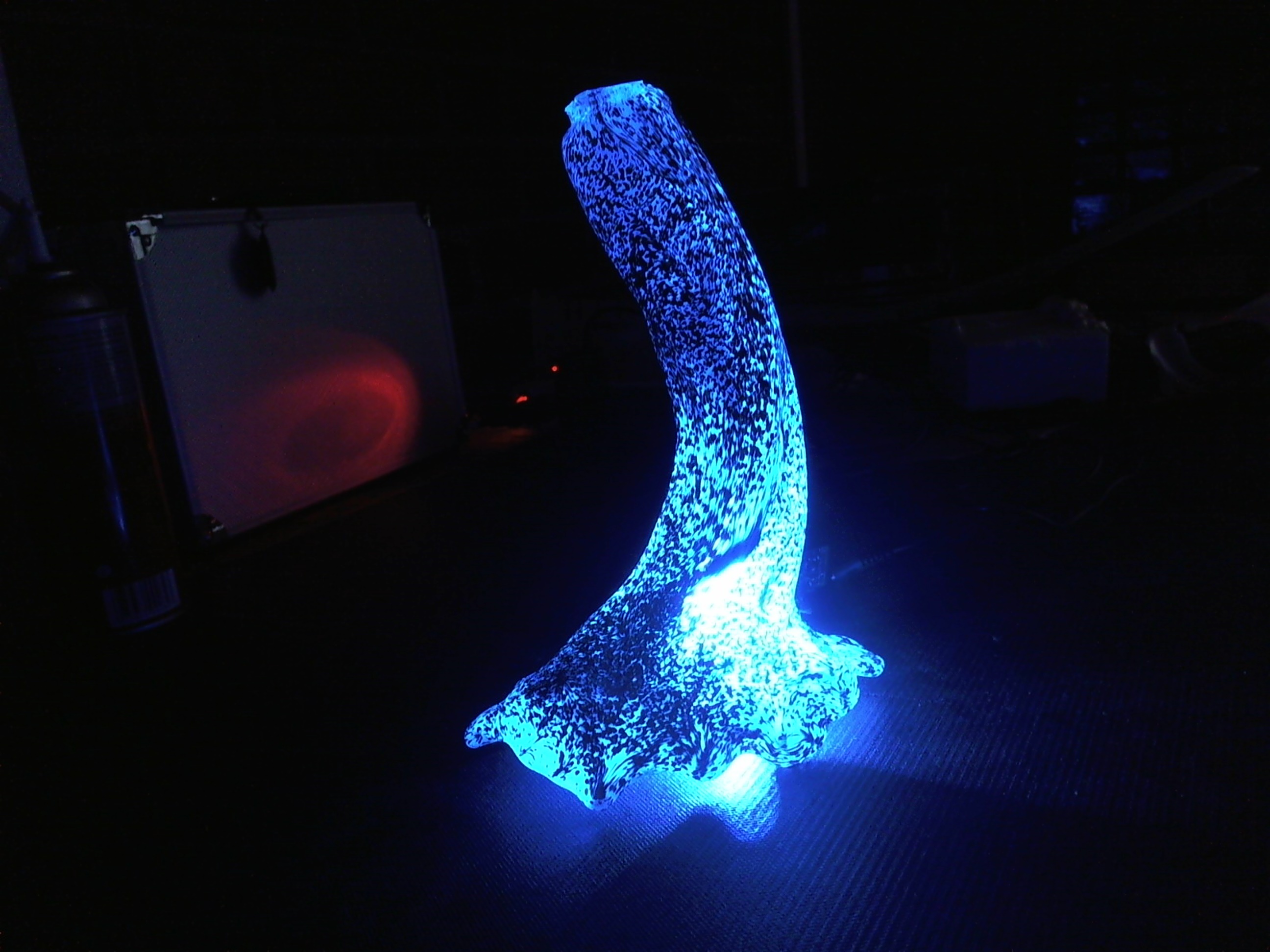 The answer for me came from working with glassblowing student Kenny Galusha last semester, when we began experimenting with illuminating some of his glass work with high-power RGB LEDs. At the time, I just hacked together a little driver using an ExtraCore RST and bits and pieces I had laying around, but pretty quickly we began having bigger and better ideas. It wasn’t long before I realized that my old RGB LED circuit board would be perfect for what we wanted to do! So I dusted off the old files and sketches and really got to work.
Revision A board design
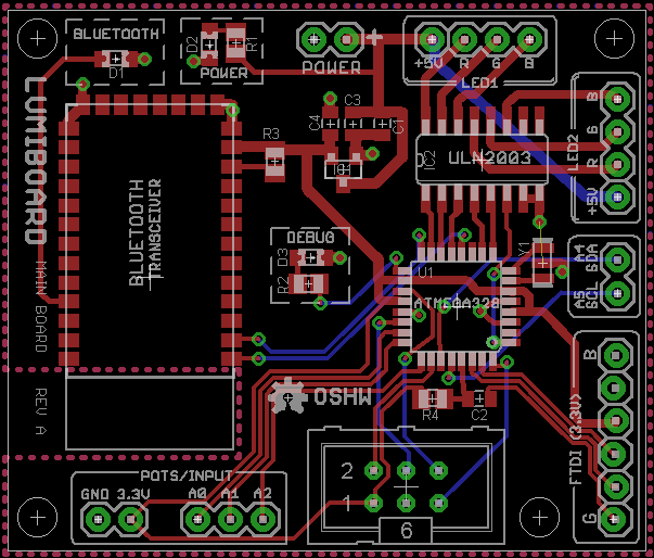
When I began this project, I really didn’t have any skills in the PCB design side of Eagle, so I had simply slapped all of my components down onto a board and used the Autorouter function to do all the hard work for me. I posted a photo to my Google+ stream and quickly started getting helpful responses from a seasoned engineer named Stew Koch. Over the next few weeks, he helped me quite a bit to learn the basics of PCB design and how to do it by hand. Needless to say, I’m still no expert, but I will always owe him a debt of gratitude for being nice enough to personally teach me the basics in Eagle!
With Stew’s help, I developed some neat board designs for both the Lumiboard main board and the sensor board. At this point, the fall semester got into full swing and I was having a hard time staying motivated to bring this project to the next level. About halfway through the semester I began collaborating with Kenny Galusha and received a nice push of motivation to start producing the boards.
Prototype PCBs from OSH Park
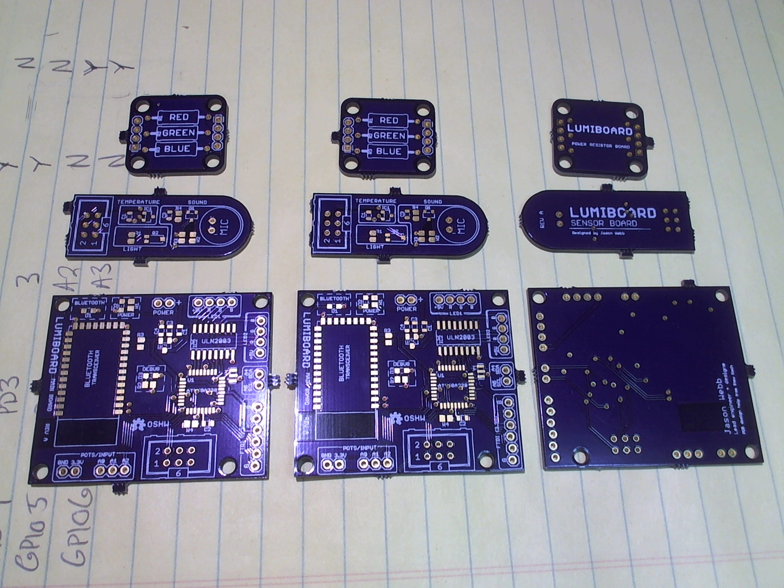
Once the board was designed, it had to be fabricated by a manufacturer somewhere. The trouble is, there is a very expensive way to do this and a cheap way. Both ways take several weeks and have their pros and cons. Luckily, two hobby-level PCB services have become extremely popular this year for me to try out: OSH Park and Seeed Studio’s Fusion PCB Service. I had already tried out Seeed Studio, and had a positive experience, but I was really impressed with the quality and recommendations for OSH Park.
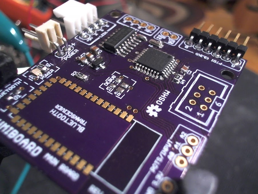
OSH Park, formerly known as Dorkbot PDX, is a PCB fabrication service offered (as far as I know) by a single person – James “Laen” Neal. The service offers beautiful purple boards, with gold contact finish, for only $5 per square inch. This gets you three copies of the board and includes free shipping!
Here is how the cost breaks down for the boards I’ve had manufactured with OSH Park:
- Lumiboard main board (1.96″ x 1.66″ = 3.2536 sq. in.) = $16.27
- Sensor board (1.69″ x 0.64″ = 1.0816 sq. in.) = $5.41
- Power resistor breakout board (0.96″ x 0.88″ = 0.8256 sq. in.) = $4.13
So, for total of $25.81, I bit the bullet and ordered three copies of my PCB design! About two weeks later they arrived, by which point I had ordered one set of parts from Digikey to assemble a single board for testing. For next to nothing, I got a nice little pile of beautiful purple and gold boards! Do I recommend OSH Park for others? Hell yes! Just keep that board size small to take advantage of the pricing structure. When you start going up about 5cm by 5cm, it is more cost effective to go with Seeed Studio, though the board quality is a little bit diminished.
Assembling and testing the first board
Because the PCBs take about 2-3 weeks to fabricate and ship, I had plenty of time for organizing and beginning the documentation for this project. I ordered a single set of parts from Digikey, who only charges less than $3 for shipping (USPS Priority). I usually receive shipments within two days from Digikey, which is really nice. Nearly all of the parts for the Lumiboard prototype are ordered from Digikey, with some cabling coming from Sparkfun. Here is how the cost breaks down for one board (minus the cost of a Bluetooth transceiver):
- Main board parts = $6.58
- Sensor board parts = $4.03
- Power resistor parts (x2) = $1.50
- Interconnects = $7.02

Flashing the Arduino bootloader onto the ATMEGA328P
Immediately, I realized a simple error – once soldered to the board, there is no way to flash the ATMEGA328P with the Arduino bootloader! Luckily, I realized this before I soldered anything, so I came up with a simple solution. I used a spare ExtraCore RST board and populated it with all the components except for the ATMEGA328. Then, I could wire up the ExtraCore for flashing the bootloader on a breadboard, and simply press the ATMEGA328 chip onto the 32-TQFN contacts to flash the bootloader. Obviously, this isn’t going to be fun for production runs, so the next revision of the Lumiboard will need to include an ICSP header for programming!
Always check those ground connections!
With the bootloader on the chip, I soldered it onto the Lumiboard prototype, along with the 8mhz resonator. I plugged in my 3.3V FTDI Basic breakout board to attempt to load an Arduino sketch, and something seemed wrong right away. The RX and TX lights on the FTDI Basic were solid and bright, and the FTDI chip itself began getting really hot. Not good.
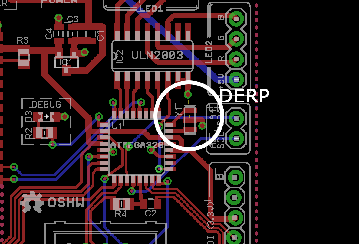
At first I thought that there was a grounding issue, so I grabbed my continuity tester and checked every ground via and trace against the main ground connection. I found out pretty quickly that the ceramic resonator was not connected to ground! I jumped back to the Eagle file and ran the Ratsnest function, and sure enough, although the resonator was connected to a via for ground, that via was isolated from the main ground plane. Very important lesson here:
Obsessively run the Ratsnest function in Eagle to make sure your ground connections are actually routed correctly!
I soldered a small jumper wire from the ground via for the resonator to a known-good ground via and checked it all again with the continuity tester – everything looked good!
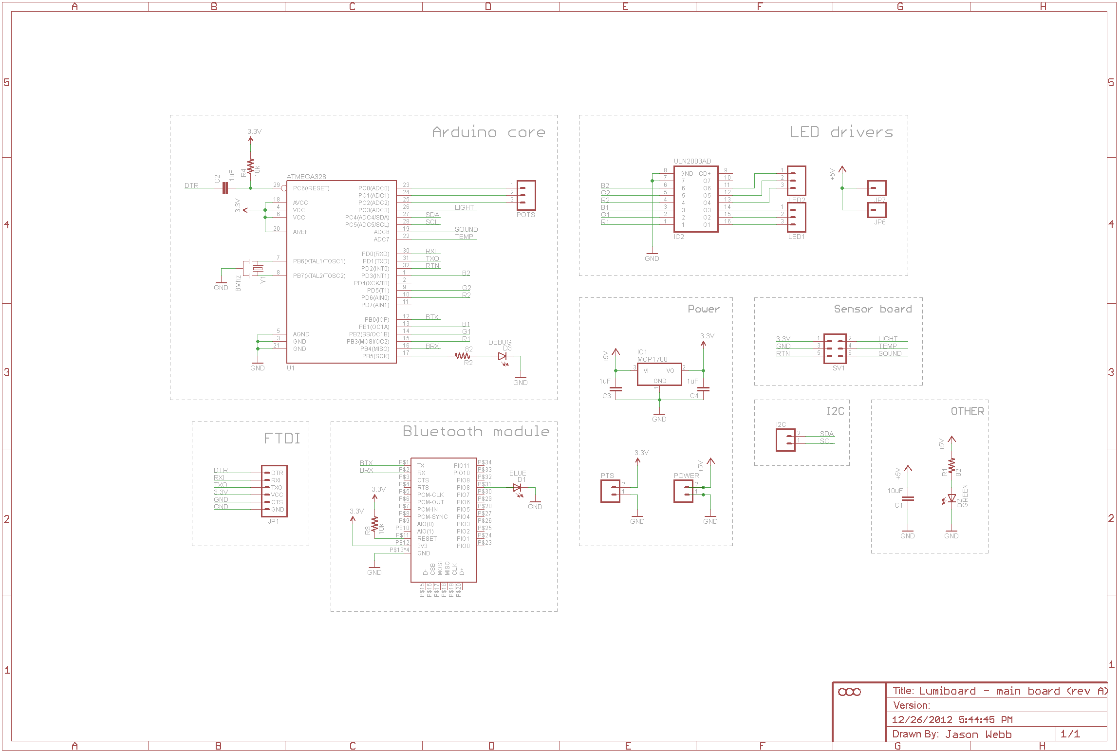
FTDI RX/TX != ATMEGA RX/TX!
I connected the FTDI Basic interface again, but the same symptoms came up. What the heck is happening? I honestly was a little stumped, so I headed over the Arduino forum and asked for some help. Sure enough, after a little discussion someone pointed out that maybe I had swapped the RX/TX lines for my FTDI interface. If you check the schematic closely, you’ll see that there are two pins on the FTDI header labelled “RXI” and “TXO”, but these don’t mean what you think it does! I assumed that meant “RX Into the Arduino” and “TX Out of the Arduino”. Apparently, it actually means “RX Into the FTDI chip” and “TX Out of the FTDI chip“!
I used male-to-female jumper wires to connect my FTDI Basic board to the Lumiboard again, this time crossing the RX and TX lines, and sure enough, it worked! I uploaded a sketch to the board that just blinks the “red” channel of one of the RGB LED ports, then ran jumper wires to an RGB LED. Success!
Lessons in interconnects: don’t get fancy
While working out the FTDI issue, I was trying to assemble some custom cables and housings that I could use to connect the Lumiboard to other components and boards more easily. I ordered what I thought were compatible housings and crimp contacts from Digikey, only to realize that I had not paid enough attention.
I ordered 2, 3 and 4-pin housings from Digikey, and one set of crimp contacts to use with all of them. However, I neglected to notice that the 2 and 4-pin housings were from a different manufacturer than the 3-pin housings! So, when I went to source the crimp contacts, I must have went to the 3-pin housing page and found matching crimp contacts through it, which were naturally different than the ones for the other housings.
Secondly, I thought it’d be cool if the connectors “snapped” onto the board, so I ordered headers that had locking tabs and housings that had ramps. What I hadn’t thought through was the fact that my two RGB LED ports (at the time) were mirrored, so the housing would need to be flipped to connect to the board correctly. But with the locking tabs and ramps, the connectors would only go on one way. Not good. So, I decided to scrap that idea and go with basic, non-gendered (and cheaper) housings and bare right-angle breakaway headers to connect to. Fun fact, you can buy 50 pieces of 40-pin breakaway right-angle male headers from DIP Micro on eBay for only $15.97 (free shipping) – that works out to $0.32 per 40-pin bar. Nice!
Next steps
I should be receiving better interconnects later today, which will let me test the rest of the prototype board functions. As I test the board out, I will be documenting all of the issues primarily through the Github repo, and occasionally be providing summary posts like this one every week or so.
If you’d like to keep up with the development of this project, here are all the best ways to do so:
- View all posts on this blog related to the Lumiboard: https://jwwpheadless.com/tag/lumiboard
- Watch the project activity on my personal wiki: https://jwwpheadless.com/wiki/index.php?title=Lumiboard
- Watch for activity on my Flickr profile: http://www.flickr.com/photos/zenwebb/
All of latest source files, as well as active bug tracking, can be found at the Github repo below: