Wall plotter update #4: pulley size calculations, ready for fabrication
I’m at the point with my wall plotter project where the virtual and theoretical information has to meet up with physical components and design considerations. In particular, now that I have the required electronics to build a wall plotter, how do we design pulleys and other mechanical components to actually make the plotter a reality? This post will be a little more detailed than previous posts, because although it is just an update, there is a bit of a thought process involved that may not make sense without a little bit of explanation. Keep in mind, this topic will be discussed in more detail in my final ‘how-to’ article, so some information may be lacking here and there.
The reason that I need to think about this topic is that I am planning to use a much cheap drive mechanism that other types of wall plotters. Der Kritzler used expensive toothed belts, and the polargraph project used expensive ball chain. Both projects required the use of a 3D printed sprocket. I realized I could save myself a lot of money by using plain old fishing wire (mono-filament), but that comes with its own price. Sandy Noble mentions that his first polargraph plotters used mono-filament, but weren’t very precise because of the size of his pulleys. Because his pulleys (actually just spools) were relatively small, the wire would wind up several times, causing very subtle, but important shifts in effective diameter. To me, the problem had an easy solution; create large enough pulleys such that the wire has enough space to wind up without overlapping and altering the diameter significantly. So the question is, how big should my pulleys be? The answer has everything to do with the specifications of the stepper motors, and the capabilities of the stepper motor drivers.
Stepper motor specifications
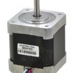
 First of all, since I have already acquired my stepper motors, I know a great deal of information about what they are capable of. The Pololu product page and accompanying datasheet lists a ton of really important information. However, in this post, I’m really only interested in one thing:
- Steps per revolution: 200
Stepper driver modes
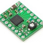
 Good-quality stepper motor drivers, like the A4988 drivers I have, are capable of a useful technique called microstepping. Basically, this means that with no changes to our control code or stepper motor, the driver can turn the motor shaft smaller amounts than would normally be possible. In particular, the A4988 stepper drivers that I chose are capable of the following step modes: full, 1/2, 1/4, 1/8 and 1/16.
If one were to set up their stepper motor driver to be in 1/8 step mode, you would be able to get 8 times the number of steps per revolution out of the same motor! The ability of the motor driver to be configured in multiple step modes means that we have a lot of flexibility over how much one ‘step’ actually ends up being.
Defining required pulley parameters
Now that we know the number of steps the motor is capable of (200), and the types of stepping modes that the motor drivers are capable of, we can think a little more about the design of the pulleys. However, it may seem like a bit of leap from identifying these bits of information and actually producing a physical pulley. There are questions that need to be answered, most important of which is “What should the diameter of the pulley be?” Luckily, there is a simple, helpful equation we can use to find this out:
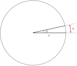
Where s = arc length, r = radius and theta = step angle
What we really want is the radius, so re-arranging the formula we get:
You can visualize this relationship in the following way:

The arc length (s) is the distance that a single point on the edge of the pulley will move per step. This variable we can actually define as whatever we want – it will directly determine the accuracy that the overall wall plotter is capable of. Personally, I wanted to have the arc length be 1mm, both for simplicity’s sake, and to stay consistent with the Der Kritzler project.
The angle (theta) is easy to get; we know that on it’s own, the stepper motor has 200 steps per revolution. To find out the exact angle per step, simply divide 360/200 to get 1.8 degrees.
Factoring in step mode
Remember that we are not limited to just 200 steps per revolution – the stepper motor drivers are capable of up to 1/16 microstepping, so we have a range of options to evaluate. Regardless of the step mode or anything else, I knew I wanted to have 1mm accuracy no matter what, so arc length (s) will stay constant at 1mm. The following table shows the radius and diameter of the pulley based on step mode:
| = User-defined | = Calculated |
Choosing a pulley diameter
Now that we have a number of choices that provide the same amount of accuracy, we need to choose the one that works best for the wall plotter. Remember that the entire point of this exercise is to try to choose a pulley that results in the least amount of ‘spooling’ or overlapping layers or wire when wound up. To really make an informed decision here, we need to know how much wire we are expecting to deal with. This will be discussed in much greater detail in the final ‘how-to’ post, but for now, suffice it to say that I have taken measurements of my installation space and determined that the diagonal distance from one motor to the opposite corner of the canvas is about 12 ft (144″).
The nearest pulley size with a circumference nearest to 144″ is the one for 1/16th mode, 40.01″ in diameter. For me, however, this seemed to me to be a bit too large to be practical. The smaller the pulley size, the more times the wire will need to spool up and overlap, so I had to be careful about how small to go. I felt that it was safe to go with 1/4 step mode, which results in a pulley diameter of 10.02″. At this size, the wire will spool up about 4.5 times, which seemed like a reasonable compromise to me.
Pulley diameter ~= 10.02″
Next steps
Now I need to actually fabricate the pulleys, which will be detailed in another post soon. The idea is simple, though: cut out two discs about 5.02″ in diamater out of a lightweight but sturdy material, and affix them to the shafts of the stepper motors. I really hope that I can come up with a simple shaft coupling mechanism to do this, so I don’t have to permanently attach the pulley to the motors. If not, I’ve got a few packs of Sugru laying around that would be perfect!
The last major component of the wall plotter system to be tackled before installation is a pen-holding carriage to be suspended between the motors, which will actually make the marks on the canvas. I have not yet thought about this too much, but will probably be thinking very hard about it over the next week or two as I fabricate the pulleys. Stay tuned!