Beginning Lampduino – early design considerations and electronics
Some time ago, I hacked together a barebones high-power RGB LED driver that could change the color of a 3W RGB LED based on RFID tags, which caused some unexpected interest in my friends and colleagues. Ever since then, I’ve been thinking about using what I learned from that project to create a simple, cheap kit that people can buy to make their very own super-bright RGB lamp. This last week, I’ve finally started taking the idea seriously and even begun working on some schematics, PCB layouts and conceptual diagrams! Not surprisingly, this last week has been full of new lessons and progress for me, which I felt I should take the time to document.
First thoughts
At first, I began by just adding things to my original project like potentiometers and a programming interface. However, as any electronics enthusiast will tell you, the more things I added, the more I realized I needed to plan out as much as I could before making the schematics. The most helpful thing I tried at this point was to get all of the electronics out of my mind and just focus on the finished product, how I envision it being used, and what I would want to see if someone else was doing this project. I came up with a list of features that I wanted to include, and thought about how the project might be used differently by hobbyists and people with very little electronics knowledge.
 I knew I wanted to create a project that might someday be worthy of putting up on a crowd-funding site like Kickstarter, which means the project would need to have a bigger vision than just another niche electronics board for electronics geeks. I felt it needed to have some amount of novelty, it needed to be interesting and it needed to be polished both conceptually and physically. I also felt it needed to be useful in more than one context; it should be open-source and well documented for the experts and hobbyists, but it also needed to be simple enough that a ‘consumer’ could just plug it in and enjoy it as a product. I want to be clear that when I say “open-source”, I don’t just mean the software. I mean everything, including the schematics, the board layouts, the software, any CNC designs and any other documentation I can think of. It would be amazing if enough people became interested in the project to add new features, extend the original functionality and help maintain the project, but I’m getting ahead of myself here.
After thinking about these things for a little while, I came up with the following list of features that I’d like to see:
- Be based on the ATMEGA328 microcontroller, so that it can be programmed using the Arduino framework
- Include a Bluetooth interface, so that the behavior of the lamp can be controlled via smartphones, tablets or any other Bluetooth-capable host device
- Support at least one 3W RGB LED
- Include three potentiometers, so that people who do not have access to the Bluetooth interface can adjust the color of the lamp anytime they want
- Include a variety of sensors that the lamp can use to react to the environment. I specifically wanted to have sensors for temperature, ambient light and sound
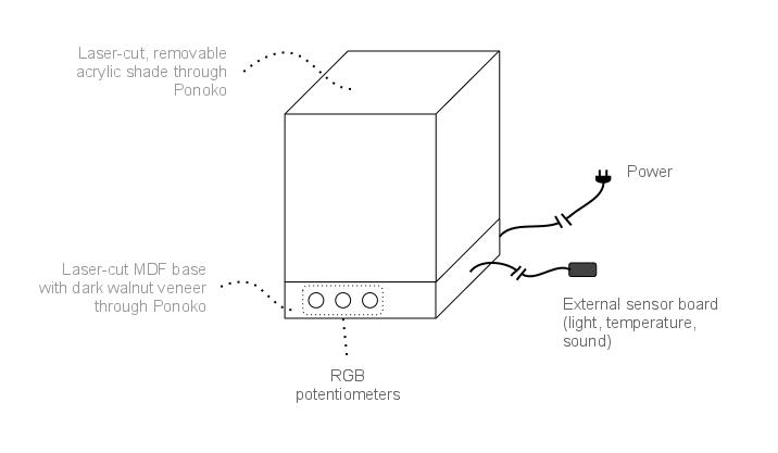
- Offer a “designer” lamp enclosure that works well and looks good
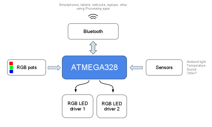
Using these soft requirements, I drew up a conceptual diagram of what I’d like the finished product to follow:
High-level overview of complete system and interactions
Now I’ve got a list of soft requirements, and a conceptual model in mind that I want the project to follow. Essentially, the project looks somewhat like a heap of puzzle pieces: we’ve got a bunch of physical parts and components, as well as “chunks” of information, all of which quite obviously fit together in some way (and possibly even in several ways). To me, it would seem that the most logical course of action is the simply start picking up each piece, one by one, and trying to fit them to the others. Over time, a coherent picture will emerge and as the number of unmatched pieces shrinks, the process will get easier and easier.
The first, obvious step towards turning this conceptual model into a physical reality is to take all of the desired features, identified above, and examine how they relate to each other. The following diagram is how that looks:
Starting the schematic and PCB layout
Once I knew what features I wanted, I began hunting down good components and the required components to make them work. Very quickly, I realized two very important things that would dictate how the schematic would need to be constructed. First, because the Bluetooth module I chose operates at 3.3V, the ATMEGA328 would need to also be operating at 3.3V in order to exchange data with it (unless level-shifting is added, which only increases parts count, not functionality). Secondly, the PCB fab house I’ve chosen to use, Seeed Studio’s Fusion PCB Service, has a price break at 5cmx5cm, which means that it would be most economical for me to try to fit my circuit into a board less than 5cmx5cm, or ~1.96×1.96″. This means that this part would greatly benefit from the use of surface-mount (SMD) parts.
It is that second point that I think has had the biggest effect on the actual board design so far, and an explosion of fun new things for me to learn. I’ve never created a board using surface-mount parts before, but I do feel like a badass for using them. Surface-mount tech is found in nearly every consumer device today, and has always had a sort of mind-blowing, almost mystical quality to me as a hobbyist. Now I get to learn about how the manufacturing process works and how to work with them by hand, and it’s great!
So far, I have switched the ATMEGA328 package to TQFP, then replaced the other ICs and passive components with their SMD packages (primarily sticking to 0603 for all the resistors and caps, though I may have to revise this if my assumptions were wrong). I rotated the ATMEGA328 45 degrees to help with the routing, and I think the autorouter is doing a great job handling everything so far.
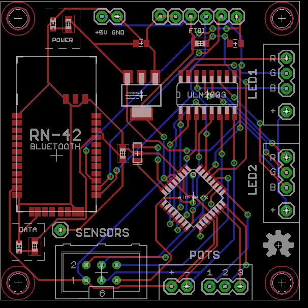
You’ll notice several important things in this version of the main electronics board right now:
- The high-power RGB LEDs and their power resistors are not on the main board. There will be breakout boards containing the resistors which can be mounted separately. This should help quite a bit with heat dissipation and keeping the board dimensions down
- All of the sensors are missing from the main board. Notice the 2×3 shrouded header in the lower left? This will connect to a tiny, separate board that contains all of the sensors, which is meant to be mounted outside of the lamp. This should help the ambient light sensor get better readings, and also help with getting accurate room temperatures as well.
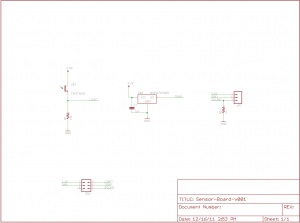
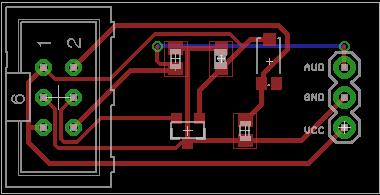
The circuits for the temperature and ambient light sensors are both from Lilypad sensor boards, because I have never worked either either of these particular sensors and would rather rely on a circuit that has been proven to work. I’ll try to clearly annotate the sources of all circuit snippets in the official documentation, once the project has progressed a bit further.
One thing that I decided to not do myself was the audio input sensor. Rather than a single sensor and one or two other parts to make it work, a microphone requires a relatively large amount of parts to either set up an op-amp or bias a transistor. Not a huge problem, but enough that I wouldn’t want to hand-solder these boards myself. Instead, I’ve opted to use the electret microphone breakout board, which will be soldered directly to the sensor board. Still quite unsure if this is a good idea or not, and would love to find a better solution to keep cost down.
Software interfaces
 Because of the ubiquity of Bluetooth in modern devices, the Lampduino should be accessible by a very large amount of people through some custom open-source software. Using my favorite software framework, Processing, will make this phase trivial, especially once it’s 2.0 version is released, which should coincide nicely with the development timeline of this project. Procsesing 2.0 will include support for Android devices and even HTML5 canvas, which means that I can create one or two sketches in Processing and export them for every major platform at the same time. Right now, I’m thinking Windows, Mac, Linux and Android will all be extremely easy to develop for. I’d like to offer an iOS app as well for all of the
 hipsters Apple fans, but I’m not sure I want to go through all of the work to make it happen. Hopefully the project will excite enough people that someone will port the Processing app I create over into an iOS app, but we’ll just have to see about that.
What to do now
The most obvious next step in this project is to finalize the PCB layout and send it off to be fabricated and begin playing with a prototype. Before I can do that, however, I want to feel 110% sure that the schematic is sound and the system will work as I expect it to. I will probably post the schematic and board layout (or pieces of it) to various forums like Arduino, Adafruit and MAKE and try to get some feedback. While this is going on, I will be continuing to learn about SMD construction techniques and hopefully come up with a very cheap method of attaching all of the SMD parts to the PCBs. Right now, my intuition leads me to believe that this will involve a cheap heat gun, some solder paste, and maybe some anti-static tweezers.
Once I’m reasonably confident in the PCB designs and the circuits in general, I’ll send the Gerber files off to the fab house and order all of the necessary parts from DigiKey. Since I expect the fab house to take at least a couple weeks to manufacture the boards, I will spend my time organizing my thoughts regarding the software, user experience, interaction design and possible Kickstarter campaign. If I’m really on my A-game, I will have enough to time to actually create a rough alpha version of the software, and hopefully start throwing the project files up on Github.
Get involved
Do you like the Lampduino project and want to lend a hand? Right now, there are two things that would help this project progress: expert feedback and funding. If you’ve ever done PCB layout design, SMD work or worked with Bluetooth connectivity with the Arduino platform, please consider looking over my work so far and sending me any advice!
The other area that I could use some help in with Lampduino is funding. I am currently a grad student, so its no surprise that funds are tight for me. If the Lampduino project sounds cool to you, any amount of funding you would be willing to donate to me would be immensely helpful in paying for the initial prototypes and components. Any funding donated to me will be directly used for prototype PCBs, components from DigiKey and SparkFun and tools for SMD construction (heat gun, tweezers, etc).
At the time of writing this article, here’s the cost breakdown of what I expect to pay:
- ~$30 to have the first batch of prototype PCBs manufactured
- ~$40 for electronics components and shipping
- <$50 for SMD-related tools and parts (heat gun, tweezers, solder paste)
Any contribution is appreciated, and you can even specify what you’d like your contribution to be used for by filling out the “Intended use” box in the checkout page. All contributors at this stage will be honored as an “Early Adopter” in future posts and project updates, and I will try to offer something for you in return based on your donation amount!
